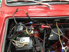
Before that chasm opened up in front of me, my target was to remedy a limp rate of charging. Then the problems rolled in.
Firstly, the alternator conversion had been executed in the tried and tested fashion: remove the regulator; join the warning light wires; and connect everythig that's left in a big, messy chocolate block connector that guarantees problems for future owners. Click on photo left to see what I mean.
More than any cosmetic challenge, it incorporates two important risks. The first is that you might be trying to jam the alternator's 35/40A down a piece of wire originally rated at about 25A before conductor oxidation and that big insulated butt-shunt in the charge cable ever pushed up its resistance. Then you lace the entire charging circuit through the bulkhead and under the dash through the series-mounted 30A ammeter. Which all sounds to me like it could get pretty toasty.
The next issue thrown up is revertibility. That's not just a question of making it look right or worrying about concours. It is the real problem of homologation standards and race regs that can make dynamos de rigeur. Model T's had alternators using trembler coils, but the good old zener diode did not come along in cars much before 1970. (Pub-quiz entrants might note that this diode is eponymously styled after its inventor - Clarence Zener) So I feel that if I am going to re-engineer this, I am going to make it swing ac/dc, if you see what I mean, so it is dynamo-optional.
So the final formula has become to use a dummy regulator box, providing a physical installation similar to the original that can be swapped for a dynamo regulator if the need arises. Wiring for the charge circuit uses two 3mm cables, making it good for 60A. And a voltmeter in the dash, rather than ammeter.
Of course, this means relocating the dodgy fusebox - which will require rewiring it etc......
 RSS Feed