Before that chasm opened up in front of me, my target was to remedy a limp rate of charging. Then the problems rolled in.
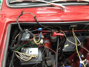
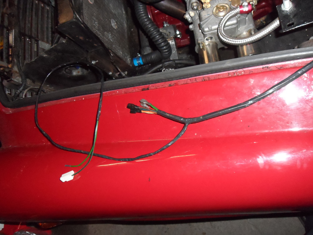
Firstly, the alternator conversion had been executed in the tried and tested fashion: remove the regulator; join the warning light wires; and connect everythig that's left in a big, messy chocolate block connector that guarantees problems for future owners. Click on photo left to see what I mean.
More than any cosmetic challenge, it incorporates two important risks. The first is that you might be trying to jam the alternator's 35/40A down a piece of wire originally rated at about 25A before conductor oxidation and that big insulated butt-shunt in the charge cable ever pushed up its resistance. Then you lace the entire charging circuit through the bulkhead and under the dash through the series-mounted 30A ammeter. Which all sounds to me like it could get pretty toasty.
The next issue thrown up is revertibility. That's not just a question of making it look right or worrying about concours. It is the real problem of homologation standards and race regs that can make dynamos de rigeur. Model T's had alternators using trembler coils, but the good old zener diode did not come along in cars much before 1970. (Pub-quiz entrants might note that this diode is eponymously styled after its inventor - Clarence Zener) So I feel that if I am going to re-engineer this, I am going to make it swing ac/dc, if you see what I mean, so it is dynamo-optional.
So the final formula has become to use a dummy regulator box, providing a physical installation similar to the original that can be swapped for a dynamo regulator if the need arises. Wiring for the charge circuit uses two 3mm cables, making it good for 60A. And a voltmeter in the dash, rather than ammeter.
Of course, this means relocating the dodgy fusebox - which will require rewiring it etc......
After spending another couple of hours painstakingly extracting one wire, and replacing it with another, I have to seek catharsis in writing this blog entry. I am tortured about whether I have gone about this the right way or not, and scope creep is threatening to imprison me.
The story is simple, charging on the car has not been very clever despite the presence of an alternator. I replaced brushes and it was no better, even recognising that the conductor rings are groovier than Austin Powers. But, paying some attention to the wiring, I realised that it still used the original dynamo wires - good for 25A. Then, tracing it back, was able to delve into the darker orifices of the engine comparment and extract great coils of harness wrapped in oil-damped woven covers, joined with a motley selection of choc-blocks, insulated butts and scotchloks. The woven cloth cover rolled off the cables between my hands and revealed half-century old wiring, its insulation withered and cracking after the migration of plasticisers.
I have seen a GRP-bodied car burn and had no choice but to open the harness up and take a further look. I resolved to do just what was necessary in the engine compartment, extracting damaged or previously-repaired wires, replacing them one at a time. But I have just been sucked into what is now a full-scale reharnessing of the frontend.
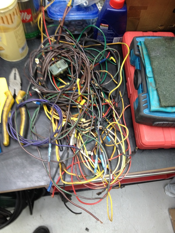
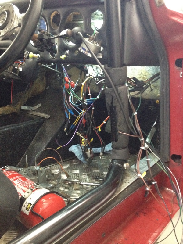
Below, on the left, is what I have taken out (and replaced) so far. A prize to whoever guesses correctly the number of scotchloks and butts when the pile is complete. Because, as the current underdash shot shows, there seems to be more to do every day....
Well that's the theory anyway. But the practice did not work out like that in the last couple of weeks.
After giving (too) many months to refurbishing my workshop, I went to start the car for the first time this year and could not get anything more than a big solenoidy 'clunk' out if it. Whatever problems I had were exacerbated by having it parked securely offsite. So no tools, no pit, hee haw.
Checked the motor was not seized (phew). And pulled out the multimeter to do a few rudimentary checks. Conclusion was that the starter motor had died. This was a recentish hi-torque starter motor, so confusing as well as disappointing. My only resort was to pull the dizzie and squeeze into that gap separating the floor from the floorpan to release the bottom mounting bolt. It came off surprisingly easy, and that's where the story really begins.
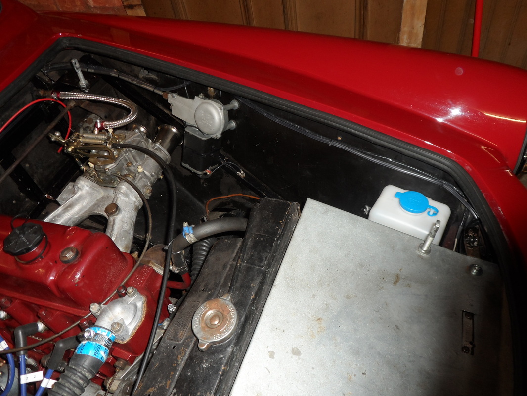
Another requirement for the car to gain its MOT (roadworthiness test) was to reinstate windscreen washers. The reservoir had long disappeared, with some of its wiring and plumbing. And the windscreen washer jet was missing, well, its jet!
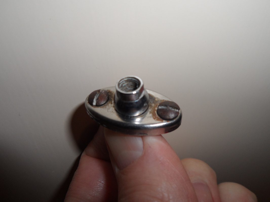
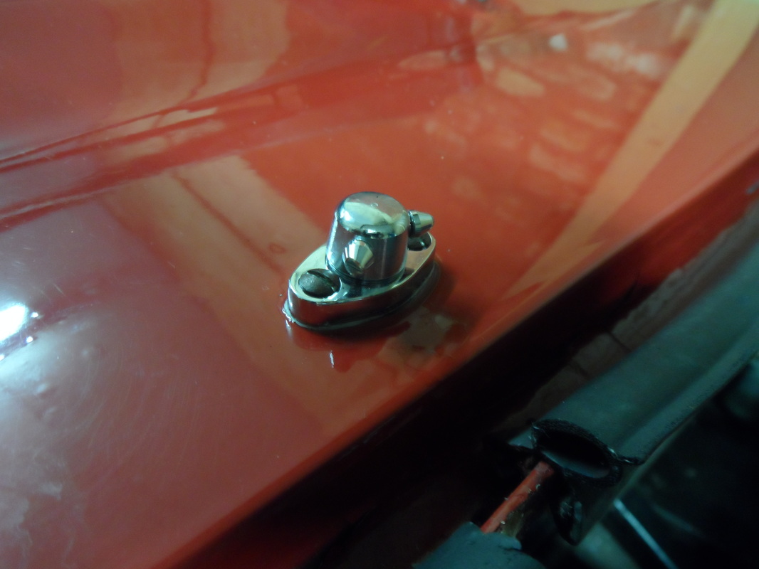
Starting with the washer jet, I found the item was common to the Daimler Dart and earlier Cobras. It was probably used on a number of other plastic cars of the era as it had the merit of being held to the bodywork by two screws. The good news was knowing its source; the bad news was finding that these are entirely unobtainable.
Fortunately, I found a substitute (designated for the Dart) from David Manners. This consisted of a small, machined pedestal that presented an 8mm hole into which a conventional twin-jet washer could be bolted. Expedient and reassuringly expensive.
The reservoir and pump should be a Lucas 2SJ, another electro-mechanical wonder of its age that delivered a measured volume of water for each 'hit' of the momentary dashboard switch. I shall save that story for another day, when I have one that is adequately restored. But, in the meanwhile, my son and I reinstated the cable runs from where they had been terminated adjacent to the wiper motor. And we fixed a cheap eBay reservoir and pump in the correct location for the 2SJ that will eventually follow.
Well, apart from their practical usefulness, they are a required part of the MoT test. Which is why I needed to make these work before I would be able to reregister the car in the UK.
When I began to investigate why they might not work, I found the answer pretty quickly as I grabbed a bundle of unconnected harness cables from below the carburetor. The real challenge was then finding that the harness connections bore no resemblance to the connections presented on the wiper motor.
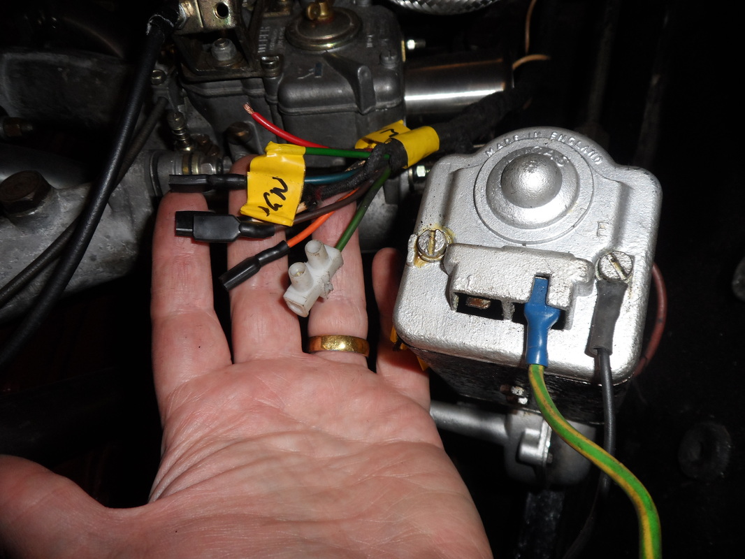 Harness connections on left. Solitary motor connections on right. | 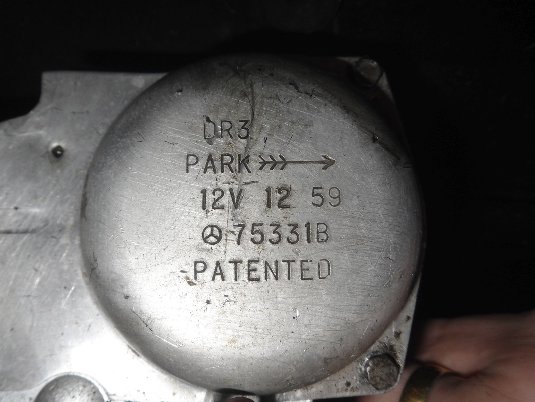 Gearbox cover says DR3. But motor itself was DR3A. |
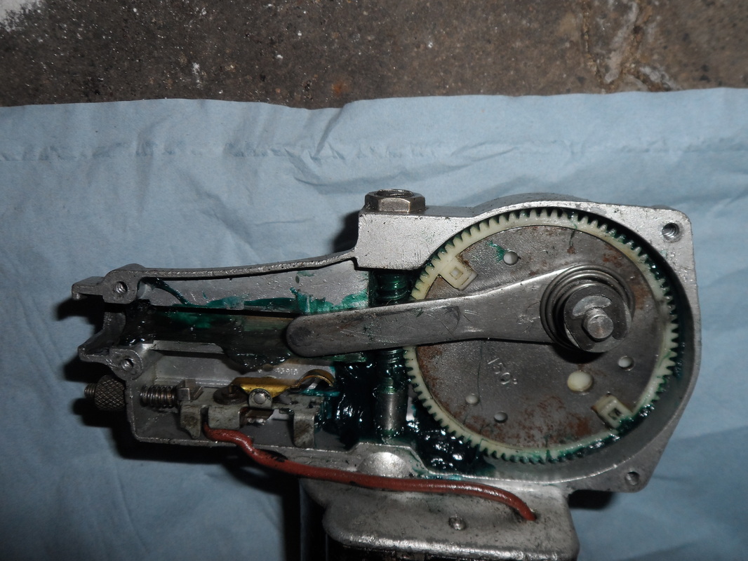
The key to all of this was that the wiper motor was actually a Lucas DR3A, regardless of what it said on the gearbox cover. The car is supposed to be fitted with a DR3. This latter motor displayed all the wizardry of mechanical engineering at the time. It has no permanent magnet, but does all sorts of interesting things by powering a field coil using a unique wiper switch.
The correct motor provides two-speed operation and 'reverse park'. The latter means when you switch it off, the motor is immediately thrown into reverse, tapping into an ignition-switched supply on the harness that is then interrupted by contacters on the internal parking finger.
There are fuller descriptions on the web. And the most useful, including a wiring diagram, I found was here....
http://www.stretton.tv/DR1%20motor.html
In any event I was rescued by Brian, the Gilbern Owners Club's GT Historian, who produced a refurbished DR3 for me. This needed only for me to switch the gear and the 'parking finger' from the original unit and to rework the original harness, restoring the some of the blade connectors and spurs for the associated washers.
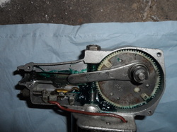
The gear (here 150 degrees) determines the sweep of the blades. Different specifications rely on how far the arm is pivoted from the central axis of the gear - varying the arc of the reciprocating arm.
And the parking finger (positioned in the lower left of the gear case) determines whether the motor parks on a 'push' or a 'pull', hence where the car the wiper blades park. There is a twiddly knob on the end for fine adjustment.

 RSS Feed